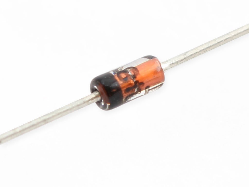
1N4148 diodes (one for each switch)
Many switch types available, choose based off of feel/purpose/sound
Ultimate Guide to Mechanical SwitchesChoose based off of aesthetics, make sure the set you're buying contains enough keys
Costar style stabilizers.
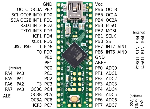
Two types of Micro-Controllers are common; Teensy 2.0 and Teensy++ 2.0. The Teensy 2.0 will work for keyboards with less than 80 keys. The rest will require a Teensy++ 2.0.
All keyboards require 3M x 8mm hex screws. Amount is dependent on keyboard, but will at most be 24.
I've had the most luck only using 20-28 awg solid core wire. I use the soldering iron to remove insulation.
Make sure it matches your Micro-Controller or you'll have to do some extra work.
Quality of soldering iron does not matter, they all work well in the right hands. Just make sure it's the "pencil" style of iron, and not the "gun" style. The pencil style is for soldering electronics, the gun style is for scorching designs in wood.
60-40 rosin core solder works best
Again, quality does not matter too much
Full Size 100% Keyboard
Keyboard Without Numpad and Function Row
60% Keyboard and the GH60 Compatible Version (Coming Soon)
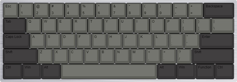
Keyboard without Numpad (Coming Soon)
Tiny Form Factor Keyboard; No Numpad, Function Row or Number Row (Coming Soon)
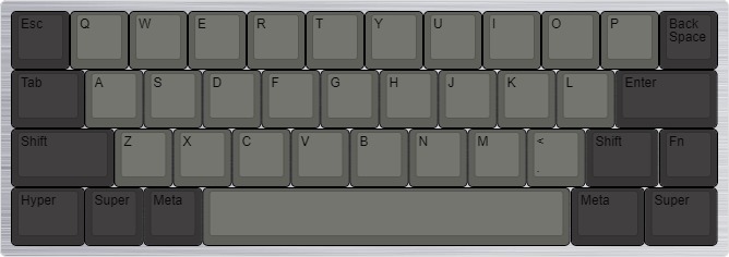
Based Off Leopold FC660 (Coming Soon)
Based Off Satisfaction 75 (Coming Soon)
Half-Keyboard for Playing League of Legends (Coming Soon)
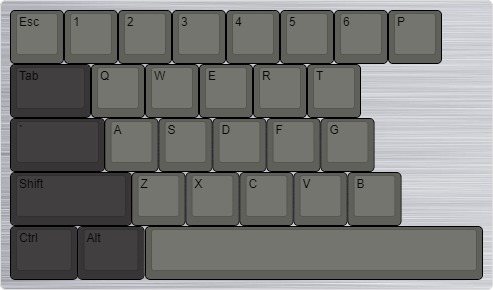
Ortholinear Board Based off of Planch (Coming Soon)
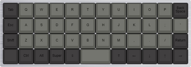
Based off Happy Hacking Keyboard Professional 2 (HHKB) (Coming Soon)
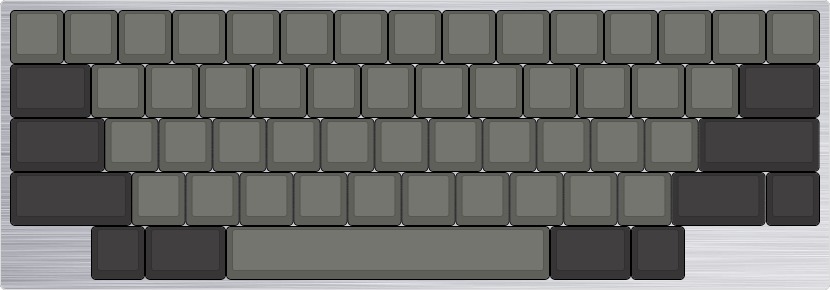
1. Heat up iron to 350-450 degrees
2. Place tip or iron so it touches both joints that need to be soldered
3. Press solder wire to point where iron and joints meet, solder should melt and be "magnetized" toward joints
4. Remove iron and solder wire, let joint harden
Beginner's Guide : How to Build a 60% Mechanical Keyboard
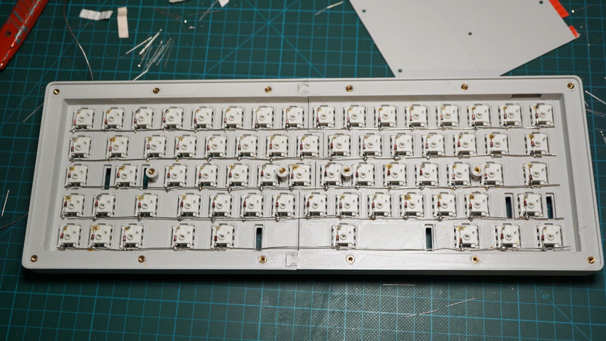
Hand-wired mechanical keyboard inside a 3d printed case
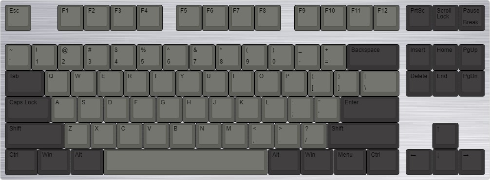
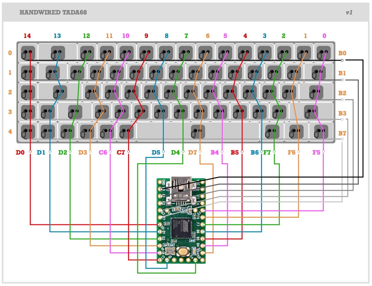
To begin, you will need a wiring diagram, a micro-controller pin diagram, and a hex file. The following were made using Keyboard layout editor, and keyboard firmware builder.
Place each switch into it's hole. You will notice from the backside that each switch has two pins. Choose which one will be the row pins and which will be the column pins. Keeping this consistent will lessen the chance of making a mistake.
We will first solder the rows. For this we will use the diodes. The wiring diagram above shows the rows as red lines. For each switch, solder a diode to it. Solder the other end to a common wire. An example of this is shown below. (Taken from matt3o.com)
Notice that each diode is painted black on one side.
This is because diodes only allow electricity to flow one way through it. Make sure that the painted black side is always pointed toward the common wire and not toward the switch.
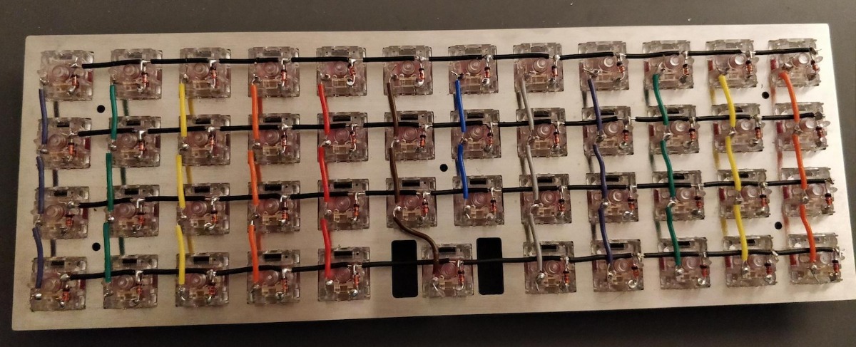
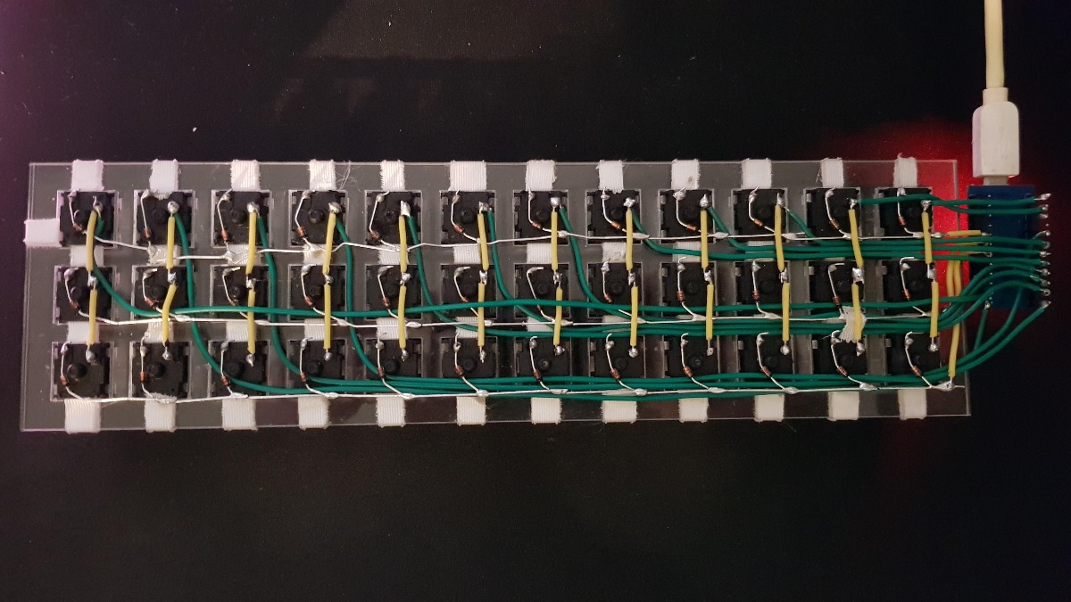
Next we will wire the columns. The black lines in the wiring diagram show which switches need to be connected. Make sure that your soldering matches the diagram. An example of completed rows + columns wiring is show below.
The final step in wiring is to wire each row and column to the correct pin. Below is a pin diagram for a teensy 2.0 ++. Refer to the pin diagram and the teensy diagram to wire each row & column to the corresponding teensy pin.
A fully wired keyboard
A diagram for the tada-68
Before you begin, make sure you have a hex file that matches your keyboard type & wiring. Download and install the latest version of Arduino & Teensyduino from the links below.
Open Arduino, make sure the right port and board are selected
Verify and program a blank sketch and blink sketch to confirm the programmer is working. (Blink sketch is located under File > Examples > 01.Basics > Blink )
Click the "Open HEX File" on the teensyduino window. Select your keyboard hex file and click "Open".
Click the "Program" button the the teensyduino window.
Hex file will be uploaded to keyboard. Screw up back of Case. Congratulations, your keyboard is complete